Posts

Showing posts with the label provisions

https://www.vultr.com

The Everywhere Cloud

Deploy an instance.
Accelerate your application.


Electrical DEAN for Mobile Devices

Image
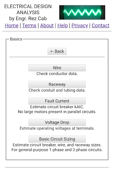
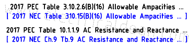
Get it on  Huawei AppGallery now! (Keyword: "ElectricalDEAN") ========== Electrical DEAN for Mobile Devices is an electrical design analysis app based on the Philippine Electrical Code, the SI Modernized Metric System, and equivalent provisions from the National Electrical Code (NFPA 70). Electrical design analysis is primarily about detailed calculations of wire gauges, conduit sizes, protective device ratings, fault currents, voltage drops and other technical matters necessary for the safe and proper operation of electrical systems. The Electrical DEAN mobile app is intended as an educational tool for those who are new in the electrical trade, and as a research tool for veterans who need quick calculations to compare with their own electrical designs. Currently, it covers the fundamentals of electrical design analysis: conductor and conduit data, fault currents and voltage drops (1-phase and 3-phase), and general-purpose circuit sizing (circui...

Standards - Note 4

Image
RACEWAY SIZES (CONDUIT AND TUBING) 1.) Raceway Sizing There are three options for sizing raceways according to 2017 PEC Table 10.1.1.1 [ or 2017 NEC Chapter 9 Table 1 ], based on cross-sectional areas: A.) 53% raceway area for 1 conductor (a multiconductor cable is treated as a single conductor [Note 9]) B.) 31% raceway area for 2 conductors C.) 40% raceway area for over 2 conductors 1.1.) Choosing Between Alternatives For future expansion purposes, option (A) is far from practical. This may have use in very specific installations that are assumed to be not needing any expansions, but upgrades will definitely happen and option (A) will eventually become a bottleneck. Option (B) for 2 conductors having a smaller area than either option (A) for 1 conductor or option (C) for over 2 conductors may seem nonsensical, but it actually does make sense. Having 2 conductors usually means 2 live wires supplying loads that may require an equipment grounding conductor ...

Standards - Note 3

Image
WIRE AMPACITIES, INSULATORS, AND IMPEDANCES Below are some useful tables pertaining to ampacities, insulators, and impedances of various wires. These are derived from the 2017 Philippine Electrical Code [ or the 2017 National Electrical Code ], but are rearranged in a manner that is easier to interpret and understand. 1.) Allowable Ampacities of Insulated Conductors in Raceway. The areas, ampacities, and insulation types of the following tables are based on 2017 PEC Table 3.10.2.6(B)(16) [ or 2017 NEC Table 310.15(B)(16) ]. 1.1.) Copper Wire Ampacities --------------------------------------- |  Copper  |  Insulation Max Op. Temp | --------------------------------------- |   Area   | 60degC | 75degC | 90degC | |   mm^2   |  Amps  |  Amps  |  Amps  | --------------------------------------- |    2.0   |    15  |    20  |    25  ...

Standards - Note 2

Image
The following items are examples listed in 2017 PEC Appendix D (Wiring Design Examples). Example D1: "Single Family Dwelling Unit, up to 50 square meters Floor Area with Load not exceeding 3,680 Volt-Amperes" Example D2: "Single Family Dwelling Unit, up to 150 square meters Floor Area (Not more than six circuits)" Example D3: "Single Family Dwelling Unit, up to 150 square meters Floor Area (More than six circuits)" Example D4: "Single Family Dwelling Unit, up to 150 square meters Floor Area, Optional Calculation" Example D5: "Single Family Dwelling Unit, more than 150 square meters Floor Area, 230 Volts, Single-Phase Service" Example D6: "Single Family Dwelling Unit, more than 150 square meters Floor Area, 400/230 Volts, Three-Phase, 4-Wire Service" Example D7: "Multi Family Dwelling Unit, 230 Volts, Single-Phase Service" Example D8: "Multi Family Dwelling Unit, 400/230 Volts, Three-Phase,...

Standards - Note 1

Image
TREATING DESIGN ANALYSIS AS MANDATORY It is important to keep in mind that, before any actual electrical work is done, everything starts at the design stage. Considerations on SAFETY and QUALITY need to be included (and examined) on paper in order to avoid any mistakes that may result in costly back jobs, or worse, loss of life and property due to electrical fire. Therefore, electrical practitioners in the Philippines need to be aware of the following provisions in the Philippine Electrical Code (PEC) concerning design analysis. ===== 2017 PEC 1.0.1.5 (A) Mandatory Rules. [ 2017 NEC 90.5 (A) ] "Mandatory rules of this Code are those that identify actions that are specifically required or prohibited and are characterized by the use of the terms SHALL or SHALL NOT." ===== 2017 PEC 1.3.2.1 (F) Plan Requirements - Design Analysis . [ This PEC provision does not exist in NEC. ] "Design analysis SHALL be included on the drawings or SHALL be submitted on se...

Terms and Conditions

Image
1. GENERAL PROVISIONS By accessing or using this website or any of its contents, you hereby agree to these terms and conditions, and consent to be bound by it. If you do not agree, you should not access or use this website. The authors of this website reserve the right to change these terms and conditions at any time without prior notice. Your continuance in accessing or using this website signifies your acceptance and agreement with these terms and conditions. The authors of this website reserve the right to change its contents, and to restrict, withdraw, cancel, disconnect, deactivate, suspend or discontinue any or all of its contents without prior notice. 2. COPYRIGHT AND FAIR USE This website is operated as a free service for the public. Some materials contained herein, however, are protected by copyright. You must abide by all the copyright notices or restrictions set by their respective copyright holders accordingly. 2.1. ORIGINAL WORKS The use and distribution, ...

Why "Design Analysis"?

Image
According to the Philippine Electrical Code (PEC), Article 1.3 (Electrical Plans and Specifications) states that the Plan Requirements (Section 1.3.2.1) are as follows: (A) Location and Site Plans (B) Legend or Symbols (C) General Notes / Specifications (D) Electrical Layout (Floor Plan) (E) Schedule of Loads (F) Design Analysis (G) One Line Diagram Details of each part shall be covered on a later post, but together, they provide a complete picture of the electrical system of a given project. Parts A, B, D and G provide a "schematic overview" of the electrical system, while parts C and E provide an "elaborate description" of the nature and components of the electrical project. Design Analysis (F), however, is the part that provides justification for the decisions made in the schematic arrangements and the component choices for the project. As such, it requires a quantitative approach to prove beyond any doubt that the electrical system is establ...