Faults - Scenario 9

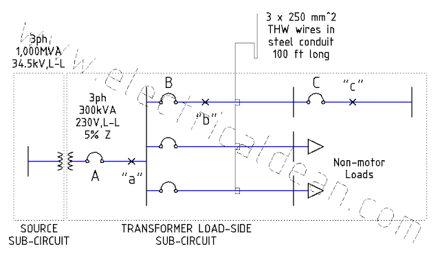
Below is a modified version of Example D14 (Simplified Fault Current Calculation) in Appendix D of the 2017 Philippine Electrical Code (PEC). This post presents a single-phase system, without any motors present in the adjacent circuits, tapping into the three-phase source. This serves as a comparison to the previous scenario where a three-phase system taps into the three-phase source. The goal here is to examine what magnitudes are to be expected in single-phase circuits compared to three-phase circuits, and how these magnitudes factor into the selection of protective device ratings. SITUATION An industrial complex receives 230 V, 60 Hz from a single-phase distribution transformer rated 300 kVA and an impedance of 5%. The transformer taps into a three-phase 34.5 kV supply with a 1,000 MVA short-circuit capacity. Using the per-unit method, what maximum symmetrical fault currents may occur in each of the fault points "a", "b", and "c"? From the...