Posts

Showing posts with the label safety

https://www.vultr.com

The Everywhere Cloud

Deploy an instance.
Accelerate your application.


Faults - Scenario 9

Image
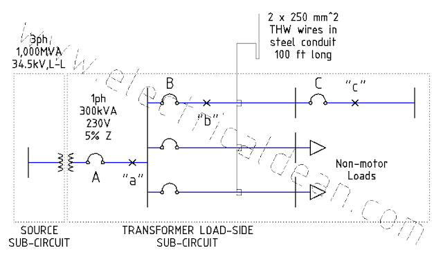
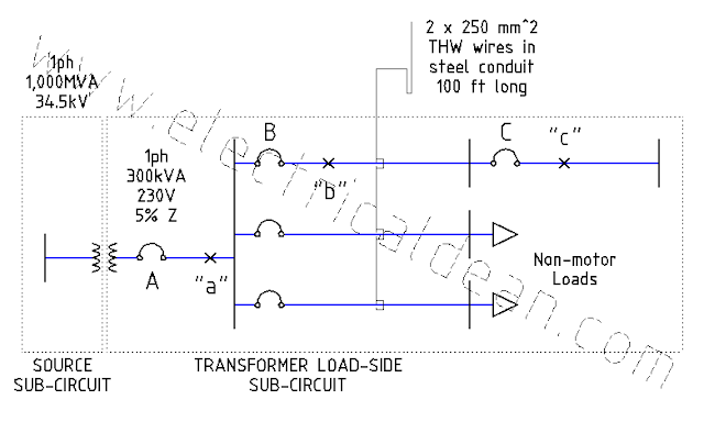
Below is a modified version of Example D14 (Simplified Fault Current Calculation) in Appendix D of the 2017 Philippine Electrical Code (PEC). This post presents a single-phase system, without any motors present in the adjacent circuits, tapping into the three-phase source. This serves as a comparison to the previous scenario where a three-phase system taps into the three-phase source. The goal here is to examine what magnitudes are to be expected in single-phase circuits compared to three-phase circuits, and how these magnitudes factor into the selection of protective device ratings. SITUATION An industrial complex receives 230 V, 60 Hz from a single-phase distribution transformer rated 300 kVA and an impedance of 5%. The transformer taps into a three-phase 34.5 kV supply with a 1,000 MVA short-circuit capacity. Using the per-unit method, what maximum symmetrical fault currents may occur in each of the fault points "a", "b", and "c"? From the...

Faults - Scenario 8

Image
Below is a modified version of Example D14 (Simplified Fault Current Calculation) in Appendix D of the 2017 Philippine Electrical Code (PEC). This post is a single-phase version of the three-phase example in the previous scenario  without any motors present in the adjacent circuits. The goal here is to examine what magnitudes are to be expected in single-phase circuits compared to three-phase circuits, and how these magnitudes factor into the selection of protective device ratings. SITUATION An industrial complex receives 230 V, 60 Hz from a single-phase distribution transformer rated 300 kVA and an impedance of 5%. The transformer taps into a single-phase 34.5 kV supply with a 1,000 MVA short-circuit capacity. Using the per-unit method, what maximum symmetrical fault currents may occur in each of the fault points "a", "b", and "c"? From these fault currents, what are the minimum symmetrical kiloAmpere Interrupting Capacity (kAIC) ratings needed fo...

Faults - Scenario 7

Image
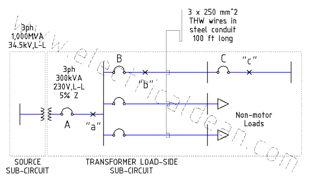
Below is a modified version of Example D14 (Simplified Fault Current Calculation) in Appendix D of the 2017 Philippine Electrical Code (PEC). This post is almost identical to the previous scenario , except that there are no motors present in the adjacent circuits. SITUATION An industrial complex receives 230 V, 60 Hz from a bank of three single-phase distribution transformers interconnected into a three-phase configuration. Each distribution transformer is rated 100 kVA, and the entire bank has an impedance of 5%. The transformer bank taps into a 34.5 kV supply with a 1,000 MVA short-circuit capacity. Using the per-unit method, what maximum symmetrical fault currents may occur in each of the fault points "a", "b", and "c"? From these fault currents, what are the minimum symmetrical kiloAmpere Interrupting Capacity (kAIC) ratings needed for each molded case circuit breaker (MCCB) A, B, and C? ANALYSIS 1.) ESTABLISH COMMON BASE VALUES. ...

Electrical DEAN for Mobile Devices

Image
Get it on  Huawei AppGallery now! (Keyword: "ElectricalDEAN") ========== Electrical DEAN for Mobile Devices is an electrical design analysis app based on the Philippine Electrical Code, the SI Modernized Metric System, and equivalent provisions from the National Electrical Code (NFPA 70). Electrical design analysis is primarily about detailed calculations of wire gauges, conduit sizes, protective device ratings, fault currents, voltage drops and other technical matters necessary for the safe and proper operation of electrical systems. The Electrical DEAN mobile app is intended as an educational tool for those who are new in the electrical trade, and as a research tool for veterans who need quick calculations to compare with their own electrical designs. Currently, it covers the fundamentals of electrical design analysis: conductor and conduit data, fault currents and voltage drops (1-phase and 3-phase), and general-purpose circuit sizing (circui...

Faults - Note 1

Image
SITUATION In 2017 PEC Appendix D Example D14 Steps 10.2.d and 10.3.d, computing the fault currents yields almost 19,000 Amperes for point "b" and 11,000 Amperes for point "c". However, this same example as presented in the previous scenario results in fault currents of only around 17,000 Amperes for point "b" and 10,000 Amperes for point "c". Why are they different? ANALYSIS 1.) PROCEDURE IN 2017 PEC EXAMPLE D14 By inspection, it can be verified that all values in 2017 PEC D14 and in the previous scenario are almost identical, except for the new motor per-unit values used in the impedance diagrams of 2017 PEC D14 Steps 10.2.b and 10.3.b. 1.1.) 2017 PEC D14 Step 8 Motor Contribution In this step, the motor per-unit impedance is initially estimated at 0.25 pu (equivalent to a 25% subtransient reactance neglecting resistance), after considering the recommendation in IEEE Std 141-1993 Section 4.5.4.1. Conversion to the common...

Faults - Scenario 6

Image
Below is a modified version of Example D14 (Simplified Fault Current Calculation) in Appendix D of the 2017 Philippine Electrical Code (PEC). This post is almost identical to the previous scenario , except that this time, an alternative common base value is used. The goal here is to show that regardless of the common base values utilized and the new per-unit values computed, the actual values remain practically the same. SITUATION An industrial complex receives 230 V, 60 Hz from a bank of three single-phase distribution transformers interconnected into a three-phase configuration. Each distribution transformer is rated 100 kVA, and the entire bank has an impedance of 5%. The transformer bank taps into a 34.5 kV supply with a 1,000 MVA short-circuit capacity. Using the per-unit method, what maximum symmetrical fault currents may occur in each of the fault points "a", "b", and "c"? From these fault currents, what are the minimum symmetrical kiloAmper...

Faults - Scenario 5

Image
This post is inspired by the 2017 Philippine Electrical Code (PEC) Appendix D Example D14 (Simplified Fault Current Calculation). While the 2017 PEC solution is straightforward, it does not explain the essence of base values and their role in per-unit conversions. This approach aims to provide clarity and hopefully enlighten confused electrical practitioners that the Per-Unit Method is a handy tool in analyzing electrical circuits of any size, from the smallest residential loops to the largest transmission networks. SITUATION An industrial complex receives 230 V, 60 Hz from a bank of three single-phase distribution transformers interconnected into a three-phase configuration. Each distribution transformer is rated 100 kVA, and the entire bank has an impedance of 5%. The transformer bank taps into a 34.5 kV supply with a 1,000 MVA short-circuit capacity. Using the per-unit method, what maximum symmetrical fault currents may occur in each of the fault points "a", "...

Standards - Note 2

Image
The following items are examples listed in 2017 PEC Appendix D (Wiring Design Examples). Example D1: "Single Family Dwelling Unit, up to 50 square meters Floor Area with Load not exceeding 3,680 Volt-Amperes" Example D2: "Single Family Dwelling Unit, up to 150 square meters Floor Area (Not more than six circuits)" Example D3: "Single Family Dwelling Unit, up to 150 square meters Floor Area (More than six circuits)" Example D4: "Single Family Dwelling Unit, up to 150 square meters Floor Area, Optional Calculation" Example D5: "Single Family Dwelling Unit, more than 150 square meters Floor Area, 230 Volts, Single-Phase Service" Example D6: "Single Family Dwelling Unit, more than 150 square meters Floor Area, 400/230 Volts, Three-Phase, 4-Wire Service" Example D7: "Multi Family Dwelling Unit, 230 Volts, Single-Phase Service" Example D8: "Multi Family Dwelling Unit, 400/230 Volts, Three-Phase,...

Standards - Note 1

Image
TREATING DESIGN ANALYSIS AS MANDATORY It is important to keep in mind that, before any actual electrical work is done, everything starts at the design stage. Considerations on SAFETY and QUALITY need to be included (and examined) on paper in order to avoid any mistakes that may result in costly back jobs, or worse, loss of life and property due to electrical fire. Therefore, electrical practitioners in the Philippines need to be aware of the following provisions in the Philippine Electrical Code (PEC) concerning design analysis. ===== 2017 PEC 1.0.1.5 (A) Mandatory Rules. [ 2017 NEC 90.5 (A) ] "Mandatory rules of this Code are those that identify actions that are specifically required or prohibited and are characterized by the use of the terms SHALL or SHALL NOT." ===== 2017 PEC 1.3.2.1 (F) Plan Requirements - Design Analysis . [ This PEC provision does not exist in NEC. ] "Design analysis SHALL be included on the drawings or SHALL be submitted on se...

Circuits - Scenario 2

Image
This post presents a simple circuit that can be thought of as a basic model for wire insulation. When insulators weaken, high voltages can push stray currents out, hence the need for insulation resistance tests. SITUATION A 40-picoFarad capacitor is connected in series with 40-ohm resistor. If the supply is 220 Volts at 60 Hertz, what is the current flowing through the circuit? ANALYSIS 1.) Capacitive reactance, vector: X-> = 1 / (jwC) = -j / (2 pi f C) 2.) Impedance, vector: Z-> = R-> + X-> Z-> = 40 + [ -j / (2 pi 60 * 40p) ] Z-> = (40 - j 66.315M) ohms Z-> = 66.315M ohms < (-89.999965) 3.) Current, vector: i-> = V-> / Z-> i-> = 220V<0 / [ 66.315M ohms < (-89.999965) ] i-> = 3.3175uA < 89.999965 CONCLUSION The current is 3.3176 microAmperes, leading.

Circuits - Scenario 1

Image
This post presents a simple circuit that can be thought of as a basic model for conductor cables in large wiring installations, such as in big residential apartments, tall commercial buildings, or wide industrial complexes, where short-circuit or ground fault currents may not be enough to kick a circuit breaker open. In such cases, the fault condition will simply become what is known as a "phantom load". It unnecessarily heats up the cable and contributes to the energy consumption even when electrical appliances are unplugged. As cable length increases, conductor resistance and reactance become more evident, hence the need to consider them carefully in wiring design calculations. SITUATION A 0.0001-henry inductor is connected in series with 40-ohm resistor. If the supply is 220 Volts at 60 Hertz, what is the current flowing through the circuit? ANALYSIS 1.) Inductive reactance, vector: X-> = jwL = j 2 pi f L 2.) Impedance, vector: Z-> = R-> + X-...

Faults - Scenario 4

Image
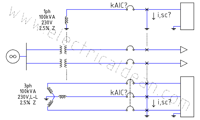
This post demonstrates how to estimate the kiloAmpere Interrupting Capacity (kAIC) rating of the first circuit breaker at the secondary side of a transformer using the Infinite Bus Method. The method assumes infinite supply from the primary side with negligible line impedances. Below is a modified version of Example D13 (Available Short Circuit Current)  in Appendix D of the 2017 Philippine Electrical Code (PEC). SITUATION Two adjacent buildings are supplied by two different distribution transformers. One transformer is single-phase rated 100kVA, 230V with 2.5% impedance. The other is three-phase rated 100kVA, 230V line-to-line and also has 2.5% impedance. What minimum kAIC ratings are needed for the first circuit breakers down the line of each transformer to safely interrupt the maximum symmetrical fault currents? ANALYSIS 1.) SINGLE-PHASE TRANSFORMER LOAD-SIDE SUB-CIRCUIT Base Power, 1ph: S,base = 100kVA Base Voltage, 1ph: V,base = 230V Impedance, ...

Faults - Scenario 3

Image
This post demonstrates how the Infinite Bus Method, shown in Appendix D Example D13 (Available Short Circuit Current) of the 2017 Philippine Electrical Code (PEC), can also be used to estimate fault currents for three-phase circuits. SITUATION A three-phase fault occurs down the line of a three-phase transformer rated 10MVA, 4.16 kiloVolts, and 5.5% impedance. What is the maximum symmetrical fault current produced? ANALYSIS 1.) TRANSFORMER LOAD-SIDE SUB-CIRCUIT Base power, 3ph: S,base = 10MVA Base voltage, LL: V,base = 4.16kV Impedance, given: Z = 5.5% 1.1.) Establishing mathematical relationships to avoid confusion: S,base = S,3ph V,base = V,LL V,LN = V,LL / sqrt(3) i,1ph = i,1L (assuming Y-config) i,base = i,1L S,3ph = 3 * V,LN * i,1ph S,3ph = 3 * ( V,LL/sqrt(3) ) * i,1L S,3ph = 3/sqrt(3) * V,LL * i,1L S,3ph = [ 3/sqrt(3) * ( sqrt(3) / sqrt(3) ) ] * V,LL * i,1L S,3ph = [ 3 * sqrt(3) / sqrt(3)^2 ] * V,LL * i,1L S,3ph = [ 3 * sqrt(3) / 3 ] * ...

Faults - Scenario 2

Image
This post is inspired by Example 10.2 of "Elements of Power System Analysis, 4th Edition" by William D. Stevenson, Jr. SITUATION A synchronous motor rated 30MVA, 13.2kV, with a SUBTRANSIENT reactance of 20%, draws 20MW with leading power factor of 80% from a feeder line with 10% reactance calculated from the machine base ratings. The line's terminal voltage is 12.8kV, and at the sending end is a synchronous generator also rated 30MVA, 13.2kV, with a SUBTRANSIENT reactance of 20%. When a 3-phase fault occurs at the motor terminals, what are the symmetrical fault currents at the generator, the motor and the fault point? ANALYSIS 1.) SOURCE SUB-CIRCUIT Base power, 3ph: S,base = 30MVA Base voltage, LL: V,base = 13.2kV 1.1.) Establishing mathematical relationships to avoid confusion: S,base = S,3ph V,base = V,LL V,LN = V,LL / sqrt(3) i,1ph = i,1L (assuming Y-config) i,base = i,1L S,3ph = 3 * V,LN * i,1ph S,3ph = 3 * ( V,LL/sqrt(3) ) * i,1L S,3ph...

Faults - Scenario 1

Image
This post is inspired by the 2017 Philippine Electrical Code (PEC) Appendix D Example D13 (Available Short Circuit Current). The 2017 PEC approach is simple and straightforward, but it does not indicate the relationships of the parameters relative to each other. This calculation is geared towards providing clarity to the confused electrical practitioner. SITUATION A fault occurs down the line of a single-phase transformer rated 100kVA, 230 Volts, and 2.5% impedance. What is the maximum symmetrical fault current produced? ANALYSIS 1.) TRANSFORMER LOAD-SIDE SUB-CIRCUIT Base power, 1ph: S,base = 100kVA Base voltage, 1ph: V,base = 230V Impedance, given: Z = 2.5% = 0.025 pu 2.) METHOD USING ACTUAL VALUES 2.1.) Base impedance, 1ph: Z,base = (V,base)^2 / S,base Z,base = (230V)^2 / 100kVA Z,base = 0.529 ohm 2.2.) Actual impedance, 1ph: Z,1ph = Z,base * Z,pu Z,1ph = 0.529 ohm * 0.025 pu Z,1ph = 0.013225 ohm 2.3.) Use rated voltage as actual vo...