Posts

Showing posts with the label schematics

https://www.vultr.com

The Everywhere Cloud

Deploy an instance.
Accelerate your application.


Faults - Scenario 9

Image
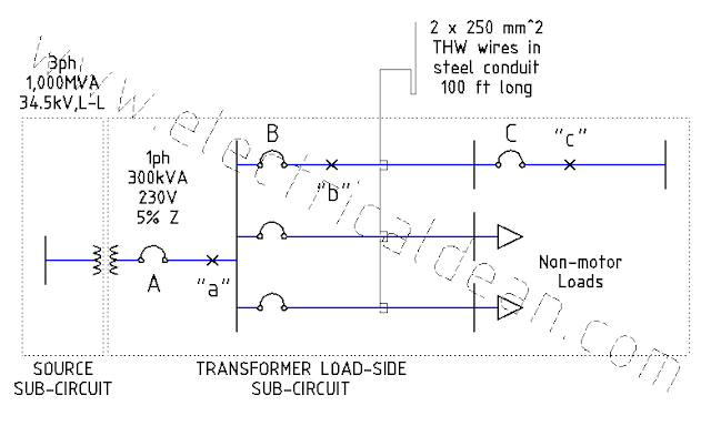
Below is a modified version of Example D14 (Simplified Fault Current Calculation) in Appendix D of the 2017 Philippine Electrical Code (PEC). This post presents a single-phase system, without any motors present in the adjacent circuits, tapping into the three-phase source. This serves as a comparison to the previous scenario where a three-phase system taps into the three-phase source. The goal here is to examine what magnitudes are to be expected in single-phase circuits compared to three-phase circuits, and how these magnitudes factor into the selection of protective device ratings. SITUATION An industrial complex receives 230 V, 60 Hz from a single-phase distribution transformer rated 300 kVA and an impedance of 5%. The transformer taps into a three-phase 34.5 kV supply with a 1,000 MVA short-circuit capacity. Using the per-unit method, what maximum symmetrical fault currents may occur in each of the fault points "a", "b", and "c"? From the...

Faults - Scenario 8

Image
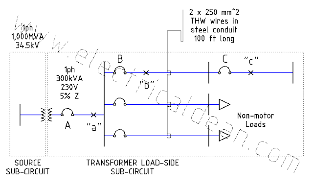
Below is a modified version of Example D14 (Simplified Fault Current Calculation) in Appendix D of the 2017 Philippine Electrical Code (PEC). This post is a single-phase version of the three-phase example in the previous scenario  without any motors present in the adjacent circuits. The goal here is to examine what magnitudes are to be expected in single-phase circuits compared to three-phase circuits, and how these magnitudes factor into the selection of protective device ratings. SITUATION An industrial complex receives 230 V, 60 Hz from a single-phase distribution transformer rated 300 kVA and an impedance of 5%. The transformer taps into a single-phase 34.5 kV supply with a 1,000 MVA short-circuit capacity. Using the per-unit method, what maximum symmetrical fault currents may occur in each of the fault points "a", "b", and "c"? From these fault currents, what are the minimum symmetrical kiloAmpere Interrupting Capacity (kAIC) ratings needed fo...

Faults - Scenario 7

Image
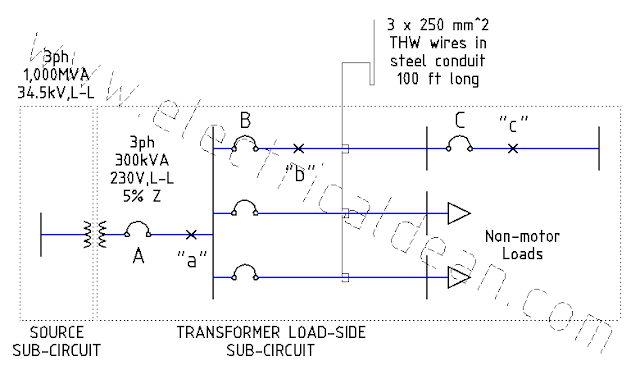
Below is a modified version of Example D14 (Simplified Fault Current Calculation) in Appendix D of the 2017 Philippine Electrical Code (PEC). This post is almost identical to the previous scenario , except that there are no motors present in the adjacent circuits. SITUATION An industrial complex receives 230 V, 60 Hz from a bank of three single-phase distribution transformers interconnected into a three-phase configuration. Each distribution transformer is rated 100 kVA, and the entire bank has an impedance of 5%. The transformer bank taps into a 34.5 kV supply with a 1,000 MVA short-circuit capacity. Using the per-unit method, what maximum symmetrical fault currents may occur in each of the fault points "a", "b", and "c"? From these fault currents, what are the minimum symmetrical kiloAmpere Interrupting Capacity (kAIC) ratings needed for each molded case circuit breaker (MCCB) A, B, and C? ANALYSIS 1.) ESTABLISH COMMON BASE VALUES. ...

Standards - Scenario 2

Image
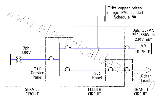
This post is inspired by the 2017 Philippine Electrical Code (PEC) Appendix D Example D12 (Voltage Regulators, Three-Phase). SITUATION A three-phase automatic voltage regulator (AVR) rated 30 kVA, 60 Hertz, 350-530 Volts input, 230 Volts output needs a feeder circuit from the main service panel. The AVR is installed in an air-conditioned data center with raised floors, and the conduit for electric conductors shall be run underneath. The wires to be used are made of copper conductors, with insulation rated for 75 degC operating temperature and of type THW (Thermoplastic, Heat-resistant, for Wet location). The raceway for the circuit is a rigid PVC Schedule 80 conduit. What size of 3ph circuit breaker, wires, and raceway are needed? ANALYSIS 1.) ONE-LINE DIAGRAM              i,avr,1L ---> o|---V,msp,LN---V,avr,LN---|> 2.) CIRCUIT CALCULATIONS 2.1.) Kirchhoff's Voltage Law, LN: -V,msp,LN + V,avr,LN = 0 V,avr,LN = V,msp,LN 2...

Standards - Scenario 1

Image
This post is inspired by the 2017 Philippine Electrical Code (PEC) Appendix D Example D11 (Voltage Regulators, Single-Phase). SITUATION A single-phase automatic voltage regulator (AVR) rated 5 kVA, 60 Hertz, 165-280 Volts input, 230 Volts output needs a feeder circuit from the main service panel. The AVR is installed in an air-conditioned data center with raised floors, and the conduit for electric conductors shall be run underneath. The wires to be used are made of copper conductors, with insulation rated for 75 degC operating temperature and of type THW (Thermoplastic, Heat-resistant, for Wet location). The raceway for the circuit is a rigid PVC Schedule 80 conduit. What size of 1ph circuit breaker, wires, and raceway are needed? ANALYSIS 1.) ONE-LINE DIAGRAM i,avr,1ph ---> o|---V,msp,1ph---V,avr,1ph---|> 2.) CIRCUIT CALCULATIONS 2.1.) Kirchhoff's Voltage Law, 1ph: -V,msp,1ph + V,avr,1ph = 0 V,avr,1ph = V,msp,1ph 2.2.) Power equation, ...

Loads - Scenario 5

Image
SITUATION It is desired to improve the power factor of a 230V, 60 Hz, 3-phase system from 0.7 to 0.92 lagging. A wye-connected capacitor bank with capacitance of 10 microfarad per phase is to be used. What is the kW of the load? ANALYSIS 1.) Capacitor reactance, 1ph: 1.1.) Scalar: X,c,1ph = 1 / (2 pi f C) X,c,1ph = 1 / (2 pi 60 * 10uF) X,c,1ph = 265.2582 ohms 1.2.) Vector: X,c,1ph-> = 265.2582 ohms / j X,c,1ph-> = -j 265.2582 ohms X,c,1ph-> = 265.2582 ohms < (-90 deg) 2.) Capacitor power, vector: 2.1) Real power The capacitor is purely a reactive device. Since there is no resistance, no power dissipation happens. Therefore, capacitor real power does not exist. P,c-> = 0 Watts 2.2.) Reactive power, 3ph: Q,c,1ph-> = V,c,LN-> (i,c,1ph->)* Q,c,3ph-> = 3 Q,c,1ph-> Q,c,3ph-> = 3 V,c,LN-> (i,c,1ph->)* -- Conjugate (i->)* means "to reverse angle sign". Q,c,3ph-> = 3 V,c,LN-> (V,c,LN-> / X,c,1ph...

Voltage - Scenario 2

Image
Below is a modified version of Example D15 (Voltage Drop Calculation) in Appendix D of the 2017 Philippine Electrical Code (PEC). This post is a single-phase version of the three-phase example in the previous scenario . The same methods in understanding schematics and applying Kirchhoff's Laws are used, with minor adjustments in the loop diagrams and voltage calculations. SITUATION A single-phase transformer supplies 230 Volts to a structure via two 250 mm^2 THWN copper conductors in steel conduit 15.2 meters long, where the main service panel draws a total of 295 Amperes. One of the circuits in the main service panel feeds a single-phase motor via two 5.5 mm^2 THWN copper conductors in steel conduit 30.5 meters long. This electric motor is rated 60 Hertz, 230 Volts, and draws a full load current of 20 Amperes at 80% power factor. How much voltage drops are felt at the main service panel and at the motor terminals, coming from the transformer? ANALYSIS 1.) ONE-LI...

Voltage - Scenario 1

Image
This post is inspired by the 2017 Philippine Electrical Code (PEC) Appendix D Example D15 (Voltage Drop Calculation). The 2017 PEC solution is straightforward, but it forces the use of daunting formulas that are easy to forget, or worse, mix up values in the process. This take on the problem removes the necessity of memorizing formulas, by guiding the confused electrical practitioner to understand the schematics, then apply the principles of KVL and KCL instead. SITUATION A three-phase transformer bank supplies 230 Volts line-line to a structure via three 250 mm^2 THWN copper conductors in steel conduit 15.2 meters long, where the main service panel draws a total of 295 Amperes. One of the circuits in the main service panel feeds a three-phase motor via three 5.5 mm^2 THWN copper conductors in steel conduit 30.5 meters long. This electric motor is rated 60 Hertz, 230 Volts line-line, and draws a full load current of 20 Amperes at 80% power factor. How much voltage drops are fel...

Faults - Note 1

Image
SITUATION In 2017 PEC Appendix D Example D14 Steps 10.2.d and 10.3.d, computing the fault currents yields almost 19,000 Amperes for point "b" and 11,000 Amperes for point "c". However, this same example as presented in the previous scenario results in fault currents of only around 17,000 Amperes for point "b" and 10,000 Amperes for point "c". Why are they different? ANALYSIS 1.) PROCEDURE IN 2017 PEC EXAMPLE D14 By inspection, it can be verified that all values in 2017 PEC D14 and in the previous scenario are almost identical, except for the new motor per-unit values used in the impedance diagrams of 2017 PEC D14 Steps 10.2.b and 10.3.b. 1.1.) 2017 PEC D14 Step 8 Motor Contribution In this step, the motor per-unit impedance is initially estimated at 0.25 pu (equivalent to a 25% subtransient reactance neglecting resistance), after considering the recommendation in IEEE Std 141-1993 Section 4.5.4.1. Conversion to the common...

Faults - Scenario 6

Image
Below is a modified version of Example D14 (Simplified Fault Current Calculation) in Appendix D of the 2017 Philippine Electrical Code (PEC). This post is almost identical to the previous scenario , except that this time, an alternative common base value is used. The goal here is to show that regardless of the common base values utilized and the new per-unit values computed, the actual values remain practically the same. SITUATION An industrial complex receives 230 V, 60 Hz from a bank of three single-phase distribution transformers interconnected into a three-phase configuration. Each distribution transformer is rated 100 kVA, and the entire bank has an impedance of 5%. The transformer bank taps into a 34.5 kV supply with a 1,000 MVA short-circuit capacity. Using the per-unit method, what maximum symmetrical fault currents may occur in each of the fault points "a", "b", and "c"? From these fault currents, what are the minimum symmetrical kiloAmper...