Faults - Scenario 5
This approach aims to provide clarity and hopefully enlighten confused electrical practitioners that the Per-Unit Method is a handy tool in analyzing electrical circuits of any size, from the smallest residential loops to the largest transmission networks.
SITUATION
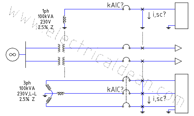
An industrial complex receives 230 V, 60 Hz from a bank of three single-phase distribution transformers interconnected into a three-phase configuration. Each distribution transformer is rated 100 kVA, and the entire bank has an impedance of 5%. The transformer bank taps into a 34.5 kV supply with a 1,000 MVA short-circuit capacity.
Using the per-unit method, what maximum symmetrical fault currents may occur in each of the fault points "a", "b", and "c"? From these fault currents, what are the minimum symmetrical kiloAmpere Interrupting Capacity (kAIC) ratings needed for each molded case circuit breaker (MCCB) A, B, and C?

ANALYSIS
1.) ESTABLISH COMMON BASE VALUES.
In order to compute everything as a unified circuit, all given per-unit values must be converted to a common base power value. However, if this new base power is equal to the existing base power, conversion is not necessary (as demonstrated in some equations below).
New base power, 3ph: S,base,new = 300 kVA
There is no need to establish a common base voltage. While the flow of power remains the same in the entire circuit by virtue of the Law of Conservation (P,in = P,out), the voltage gets affected by the turns ratio of every transformer it passes.
It is, therefore, wiser to use the existing base voltage of each sub-circuit as the "new" base voltage itself, than to establish a common base voltage for all only to have it converted with the turns ratio of each transformer sub-circuit that needs to be examined.
By retaining the existing base voltages, the per-unit supply voltage for each sub-circuit is pegged at 1 pu.
2.) CONVERT PER-UNIT VALUES FROM THE GIVEN BASE VALUE TO THE COMMON BASE VALUE.
2.1.) SOURCE SUB-CIRCUIT
Actual power, 3ph: S,src,3ph = 1,000 MVA
Actual voltage, LL: V,src,LL = 34.5 kV
Actual impedance, 1ph: Z,src,1ph = (V,src,LL)^2 / S,src,3ph
For the source sub-circuit, the actual values can be used as given base values.
Base power, 3ph: S,base = S,src,3ph
Base voltage, LL: V,base = V,src,LL
Base impedance, 1ph: Z,base = (V,base)^2 / S,base
2.1.1.) Source impedance, given, per-unit:
Z,src,pu = Z,src,1ph / Z,base
Z,src,pu = [ (V,src,LL)^2 / S,src,3ph ] / [ (V,base)^2 / S,base ]
Z,src,pu = [ (V,src,LL)^2 / S,src,3ph ] / [ (V,src,LL)^2 / S,src,3ph ]
Z,src,pu = 1 pu
2.1.2.) Source impedance, new, per-unit:
Z,src,new,pu = Z,src,1ph / Z,base,new
Z,src,new,pu = Z,src,pu * Z,base / Z,base,new
Z,src,new,pu = Z,src,pu * (V,base^2 / S,base) / (V,base^2 / S,base,new)
Z,src,new,pu = Z,src,pu * V,base^2 * S,base,new / (V,base^2 * S,base)
Z,src,new,pu = Z,src,pu * S,base,new / S,src,3ph
Z,src,new,pu = 1 * 300 kVA / 1,000 MVA
Z,src,new,pu = 0.0003 pu
2.2.) TRANSFORMER LOAD-SIDE SUB-CIRCUIT
Base power, 3ph: S,base = 300 kVA
Base voltage, LL: V,base = 230 V
Base impedance, 1ph: Z,base = (V,base)^2 / S,base
2.2.1.) Transformer impedance, given, per-unit: Z,xmr,pu = 5% = 0.05 pu
2.2.2.) Transformer impedance, new, per-unit:
Z,xmr,new,pu = Z,xmr,1ph / Z,base,new
Z,xmr,new,pu = Z,xmr,pu * Z,base / Z,base,new
Z,xmr,new,pu = Z,xmr,pu * (V,base^2 / S,base) / (V,base^2 / S,base,new)
Z,xmr,new,pu = Z,xmr,pu * V,base^2 * S,base,new / (V,base^2 * S,base)
Z,xmr,new,pu = Z,xmr,pu * S,base,new / S,base
Z,xmr,new,pu = 0.05 pu * 300 kVA / 300 kVA
Z,xmr,new,pu = 0.05 pu
2.2.3.) Conductor impedance, 1L:
For the cable conductors in the load-side circuit, their specifications are 250 mm^2 THW in steel conduit at 100 ft long (30.4878 m).
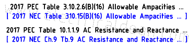
According to 2017 PEC Table 10.1.1.9 [ or 2017 NEC Chapter 9 Table 9 ] AC Resistance and Reactance for 600 V Cables, the resistance and reactance for such specification are 0.029 ohms per 305 meters and 0.048 ohms per 305 meters, respectively. [ 305 meters ~= 1,000 feet ]
Z,wire,1L = [ (0.029 + j0.048) ohms / 305 m ] * 30.5 m
Z,wire,1L = (0.0029 + j0.0048) ohms
Z,wire,1L = 0.005608 ohms < 58.86 deg
2.2.4.) Conductor impedance, per-unit:
Z,wire,pu = Z,wire,1L / Z,base,new
Z,wire,pu = Z,wire,1L / (V,base^2 / S,base,new)
Z,wire,pu = 0.005608 ohms / (230V^2 / 300 kVA)
Z,wire,pu = 0.0318 pu
2.3.) MOTOR SUB-CIRCUIT
Base power, 3ph: S,base = 100 kVA
Base voltage, LL: V,base = 230 V
Base impedance, 1ph: Z,base = (V,base)^2 / S,base
2.3.1.) Motor impedance, given, per-unit:
In 2017 PEC Appendix D Example D14, the per-unit impedance of each motor is not directly specified, but it gives us a clue on where the estimate is acquired: "IEEE Std 141".
IEEE Std 141-1993 (IEEE Recommended Practice for Electric Power Distribution for Industrial Plants) Section 4.5.4.1 (First-cycle Duties for Fuses and Circuit Breakers) Paragraph 5 states that:
"The low-voltage circuit breaker application guide, IEEE Std C37.13-1981, recommends subtransient impedances (typically 0.16 to 0.20 per unit) for all motors and allows estimates of typical symmetrical first-cycle contributions from connected low-voltage motors to substation bus short circuits at 4 times rated current (the equivalent of 0.25 per unit impedance)."
In determining circuit breaker fault interrupting capacity, the fault current during the first cycle is usually the biggest concern, and so its equivalent per-unit impedance is used accordingly.
Z,mtr,pu = 0.25 pu
2.3.2.) Motor impedance, new, per-unit:
Z,mtr,new,pu = Z,mtr,1ph / Z,base,new
Z,mtr,new,pu = Z,mtr,pu * Z,base / Z,base,new
Z,mtr,new,pu = Z,mtr,pu * (V,base^2 / S,base) / (V,base^2 / S,base,new)
Z,mtr,new,pu = Z,mtr,pu * V,base^2 * S,base,new / (V,base^2 / S,base)
Z,mtr,new,pu = Z,mtr,pu * S,base,new / S,base
Z,mtr,new,pu = 0.25 pu * 300 kVA / 100 kVA
Z,mtr,new,pu = 0.75 pu
3.) FAULT CALCULATIONS
3.1.) AT FAULT POINT "a"
3.1.1.) One-line diagram for circuit at fault point "a":
o|---V,pu---Z,a,pu---"a"---|>

o|---V,pu---Z,src,new,pu---Z,xmr,new,pu---"a"---|>
3.1.2.) Short-circuit current at fault point "a", per-unit:
i,a,pu = V,pu / Z,a,pu
i,a,pu = V,pu / (Z,src,new,pu + Z,xmr,new,pu)
i,a,pu = 1 / (0.0003 + 0.05)
i,a,pu = 19.8807 pu
3.1.3.) Short-circuit current at fault point "a", 1L:
i,a,sc = i,a,pu * i,base,new
i,a,sc = i,a,pu * S,base,new / (sqrt(3) * V,base)
i,a,sc = 19.8807 pu * 300 kVA / (sqrt(3) * 230 V)
i,a,sc = 14,971.4707 Amps
i,a,sc = 14.971 kiloAmps
3.1.4.) Minimum interrupting capacity of MCCB A:
3-phase molded case circuit breaker A >= 15 kAIC symmetrical
3.2.) AT FAULT POINT "b"
3.2.1.) One-line diagram for circuit at fault point "b":
o|---V,pu---Z,b,pu---"b"---|>

o|---V,pu---|---Z,src,new,pu---Z,xmr,new,pu---|---"b"---|>
            |----Z,mtr1,new,pu---Z,wire,pu----|
            |----Z,mtr2,new,pu---Z,wire,pu----|
3.2.2.) Short-circuit current at fault point "b", per-unit:
i,b,pu = V,pu / Z,b,pu
Z,b,pu = (Z,src,new,pu + Z,xmr,new,pu) || (Z,mtr1,new,pu + Z,wire,pu) || (Z,mtr2,new,pu + Z,wire,pu)
Z,b,pu = 1 / [ 1/(Z,src,new,pu + Z,xmr,new,pu) + 1/(Z,mtr1,new,pu + Z,wire,pu) +1/(Z,mtr2,new,pu + Z,wire,pu) ]
Z,b,pu = 1 / [ 1/(0.0003 + 0.05) + 1/(0.75 + 0.0318) + 1/(0.75 + 0.0318) ]
Z,b,pu = 0.04457 pu
i,b,pu = 1 / 0.04457
i,b,pu = 22.4366 pu
3.2.3.) Short-circuit current at fault point "b", 1L:
i,b,sc = i,b,pu * i,base,new
i,b,sc = i,b,pu * S,base,new / (sqrt(3) * V,base)
i,b,sc = 22.4366 pu * 300 kVA / (sqrt(3) * 230 V)
i,b,sc = 16,896.2309 Amps
i,b,sc = 16.896 kiloAmps
[ Note: In 2017 PEC Appendix D Example D14 Step 10.2.d, this fault current is around 19,000 Amps. This discrepancy will be tackled in another post. ]
3.2.4.) Minimum interrupting capacity of MCCB B:
3-phase molded case circuit breaker B >= 17 kAIC symmetrical
3.3.) AT FAULT POINT "c"
3.3.1.) One-line diagram for circuit at fault point "c":
o|---V,pu---Z,c,pu---"c"---|>

o|---V,pu---|---Z,src,new,pu---Z,xmr,new,pu---|---Z,wire,pu---"c"---|>
            |----Z,mtr1,new,pu---Z,wire,pu----|
            |----Z,mtr2,new,pu---Z,wire,pu----|
3.3.2.) Short-circuit current at fault point "c", per-unit:
i,c,pu = V,pu / Z,c,pu
Z,c,pu = [ (Z,src,new,pu + Z,xmr,new,pu) || (Z,mtr1,new,pu + Z,wire,pu) || (Z,mtr2,new,pu + Z,wire,pu) ] + Z,wire,pu
Z,c,pu = [ 1 / [ 1/(Z,src,new,pu + Z,xmr,new,pu) + 1/(Z,mtr1,new,pu + Z,wire,pu) +1/(Z,mtr2,new,pu + Z,wire,pu) ] ] + Z,wire,pu
Z,c,pu = [ 1 / [ 1/(0.0003 + 0.05) + 1/(0.75 + 0.0318) + 1/(0.75 + 0.0318) ] ] + 0.0318
Z,c,pu = 0.04457 + 0.0318
Z,c,pu = 0.07637 pu
i,c,pu = 1 / 0.07637
i,c,pu = 13.0941 pu
3.3.3.) Short-circuit current at fault point "c", 1L:
i,c,sc = i,c,pu * i,base,new
i,c,sc = i,c,pu * S,base,new / (sqrt(3) * V,base)
i,c,sc = 13.0941 pu * 300 kVA / (sqrt(3) * 230 V)
i,c,sc = 9,860.7159 Amps
i,c,sc = 9.861 kiloAmps
[ Note: In 2017 PEC Appendix D Example D14 Step 10.3.d, this fault current is around 11,000 Amps. This discrepancy will be tackled in another post. ]
3.3.4.) Minimum interrupting capacity of MCCB C:
3-phase molded case circuit breaker C >= 10 kAIC symmetrical
CONCLUSION
The maximum symmetrical fault currents are 14.971 kiloAmperes at point "a", 16.896 kiloAmperes at point "b", and 9.861 kiloAmperes at point "c".
The minimum symmetrical kiloAmpere Interrupting Capacity ratings needed then is 15 kAIC for 3ph MCCB A, 17 kAIC for 3ph MCCB B, and 10 kAIC for 3ph MCCB C.
For comparison, this next scenario demonstrates that an alternative common base value can be used. Although it produces different new per-unit values, it will still yield practically the same actual results.
==========
REFERENCES
1.) Philippine Electrical Code (SI Modernized Metric System)
1.1.) 2017 PEC Table 10.1.1.9 Alternating-Current Resistance and Reactance for 600-Volt Cables, 3-Phase, 60Hz, 75degC - Three Single Conductors in Conduit.
1.2.) 2017 PEC Appendix D Example D14 Simplified Fault Current Calculation.
2.) National Electrical Code (US Inch-Pound System)
2.1.) 2017 NEC Chapter 9 Table 9 Alternating-Current Resistance and Reactance for 600-Volt Cables, 3-Phase, 60Hz, 75degC (167degF) - Three Single Conductors in Conduit.
2.2.) [Not found in 2017 NEC Annex D] (Simplified Fault Current Calculation).
3.) IEEE Std 141-1993: IEEE Recommended Practice for Electric Power Distribution for Industrial Plants
3.1.) IEEE Std 141-1993 Section 4.5.4.1 First-cycle Duties for Fuses and Circuit Breakers.

Comments
Post a Comment